Select a topic below to read the Frequently Asked Questions.
Select a topic below to read the Frequently Asked Questions.
Virtually none. West·Bond equipment is designed to provide many years of hassle free operation. However, general cleanliness of the equipment is promoted and the following suggested actions will effect this end.
Note! The ball joint is the only point on a “C” series machine that requires lubrication.
ABSOLUTELY! Your West·Bond machine came with special shipping blocks, screws, warning tags, and foam just for this purpose. Refer to your owners’ manual for details on installation of these blocks and other shipping procedures. If you have misplaced these blocks contact West·Bond and order a replacement set. Note! Moving or transporting your West·Bond machine without first taking the appropriate steps can cause serious damage. If in doubt, stop and call West·Bond technical support. They will be happy to guide you in the proper care and protection of your West·Bond equipment.
Linear Bearings – Turn the machine power off and, with your right hand, firmly grasp the manipulator arm. With you thumb and forefinger of your left hand, gently grab the head assembly and move back and forth (left to right). There should be no slop between the movement of the head and the movement of the manipulator. If play is detected, contact your local representative or West·Bond technical support and schedule a service appointment.
Turn machine power on and place the machine in Calibrate mode. Open the cover. Locate the P/N 8840 PCB board toward left side of the main support. Lift the head assembly off the load cell. Adjust RT1 on the 8840 board until the display reads zero. Gently set the head down against the load cell and adjust the tare weight (spring force nut on the back side of the tool head) to 20 grams. Using the provided weight set, place a 50-gram weight directly above the hook on the tooling head. Adjust RT2 (offset) on the 8840 board until the display reads 70. Remove the weight and verify the load cell calibration by checking to see that the display now reads 20 grams. Double check using a 20-gram weight set atop the tooling head- the display should read 40 grams. Adjust RT2 accordingly, being sure to check the calibration after each adjustment. This is a delicate calibration procedure that requires a bit of finesse on the operator’s part.
This series includes: 7476D and 7700D.
Virtually none. West·Bond equipment is designed to provide many years of hassle free operation. However, general cleanliness of the equipment is promoted and the following suggested actions will effect this end.
Note! The ball joint is the only point on a “C” series machine that requires lubrication.
ABSOLUTELY! Your West·Bond machine came with special shipping blocks, screws, warning tags, and foam just for this purpose. Refer to your owners’ manual for details on installation of these blocks and other shipping procedures. If you have misplaced these blocks contact West·Bond and order a replacement set. Note! Moving or transporting your West·Bond machine without first taking the appropriate steps can cause serious damage. If in doubt, stop and call West·Bond technical support. They will be happy to guide you in the proper care and protection of your West·Bond equipment.
Linear Bearings – Turn the machine power off and, with your right hand, firmly grasp the manipulator arm. With you thumb and forefinger of your left hand, gently grab the head assembly and move back and forth (left to right). There should be no slop between the movement of the head and the movement of the manipulator. If play is detected, contact your local representative or West·Bond technical support and schedule a service appointment.
Check the connection between the transducer and the ultrasonic board. Do this by first opening the machine cover, then disconnect J2. Using an ohmmeter, check the continuity of the wires from the now open ended connector to the crystal stack on the transducer. If high resistance is found, on one or both of the wires, there is an open somewhere along the wire path. Carefully trace the wire route and ensure it is not cut or pinched. If the wires check out, reconnect J2 and calibrate the ultrasonic board. The calibration instructions are available in Adobe PDF format and require Adobe Acrobat Reader to view. Click on the link below to download.
– P/N 10345 Rev G
Virtually none. West·Bond equipment is designed to provide many years of hassle free operation. However, general cleanliness of the equipment is promoted and the following suggested actions will effect this end.
Note! The ball joint is the only point on a “C” series machine that requires lubrication.
ABSOLUTELY! Your West·Bond machine came with special shipping blocks, screws, warning tags, and foam just for this purpose. Refer to your owners’ manual for details on installation of these blocks and other shipping procedures. If you have misplaced these blocks contact West·Bond and order a replacement set. Note! Moving or transporting your West·Bond machine without first taking the appropriate steps can cause serious damage. If in doubt, stop and call West·Bond technical support. They will be happy to guide you in the proper care and protection of your West·Bond equipment.
Linear Bearings – Turn the machine power off and, with your right hand, firmly grasp the manipulator arm. With you thumb and forefinger of your left hand, gently grab the head assembly and move back and forth (left to right). There should be no slop between the movement of the head and the movement of the manipulator. If play is detected, contact your local representative or West·Bond technical support and schedule a service appointment.
Check the connection between the transducer and the ultrasonic board. Do this by first removing the cover from the left side of the machine, then disconnect J2. Using an ohmmeter, check the continuity of the wires from the now open ended connector to the crystal stack on the transducer. If high resistance is found, on one or both of the wires, there is an open somewhere along the wire path. Carefully trace the wire route and ensure it is not cut or pinched. If the wires check out, reconnect J2 and calibrate the ultrasonic board. The calibration instructions are available in Adobe PDF format and require Adobe Acrobat Reader to view. Click on the link below to download.
– P/N 6795
– P/N 10344
– P/N 10344 Rev C
– P/N 10345 Rev C
– P/N 10345 Rev D/E
– P/N 11952 Rev A/B
– P/N 11952H Rev A/B
7367E: If the Calibration Work holder is not attached to the machine, power off the system and connect the work holder to the back panel. Press the PREV key. This selects the tweezer tool head of the 7367E. Once this is done press the EDIT button. This will put the machine in the Force Calibration mode for the Load Cell work holder. Note the force displayed, if the force is not zero, ensure that there is no weight being applied to the load cell, adjust the RT1 on the load cell board until the force reads zero. Place the weight holder on the calibrate fixture and adjust the screw until there is no pressure on the load cell, Place a 20 gram weight and adjust gain RT2 for a reading of 40g. Remove and repeat as necessary.
70PTE: Turn machine power on and place the machine in Calibrate mode. Open the cover. Locate the P/N 8840 PCB board toward left side of the main support. Lift the head assembly off the load cell. Adjust RT1 on the 8840 board until the display reads zero. Gently set the head down against the load cell and adjust the tare weight (spring force nut on the top of the tool head) to 20 grams. Using the provided weight set, place a 50-gram weight directly above the hook on the tooling head. Adjust RT2 (offset) on the 8840 board until the display reads 70. Remove the weight and verify the load cell calibration by checking to see that the display now reads 20 grams. Double check using a 20-gram weight set atop the tooling head- the display should read 40 grams. Adjust RT2 accordingly, being sure to check the calibration after each adjustment.
Virtually none. West·Bond equipment is designed to provide many years of hassle free operation. However, general cleanliness of the equipment is promoted and the following suggested actions will effect this end.
Note! The ball joint is the only point on a “C” series machine that requires lubrication.
ABSOLUTELY! Your West·Bond machine came with special shipping blocks, screws, warning tags, and foam just for this purpose. Refer to your owners’ manual for details on installation of these blocks and other shipping procedures. If you have misplaced these blocks contact West·Bond and order a replacement set. Note! Moving or transporting your West·Bond machine without first taking the appropriate steps can cause serious damage. If in doubt, stop and call West·Bond technical support. They will be happy to guide you in the proper care and protection of your West·Bond equipment.
Linear Bearings – Turn the machine power off and, with your right hand, firmly grasp the manipulator arm. With you thumb and forefinger of your left hand, gently grab the head assembly and move back and forth (left to right). There should be no slop between the movement of the head and the movement of the manipulator. If play is detected, contact your local representative or West·Bond technical support and schedule a service appointment.
Check the connection between the transducer and the ultrasonic board. Do this by first removing the cover from the left side of the machine, then, disconnect J2. Using an ohmmeter, check the continuity of the wires from the now open ended connector to the crystal stack on the transducer. If high resistance is found on one or both of the wire, there is an open somewhere along the wire path. Carefully trace the wire route and ensure it is not cut, pinched, or otherwise disconnected. If the wires do check out, reconnect J2 and calibrate the ultrasonic board. The calibration instructions are available in Adobe PDF format and require Adobe Acrobat Reader to view. Click on the link below to download:
– P/N 6795
– P/N 9060
– P/N 10344
– P/N 10345
This problem is caused by a number of factors. The first is gram force. A very low gram force (15 grams or less) can sometimes cause this problem to occur. The second contributing factor is speed. If increasing your gram force does not work or you cannot increase the gram force, try slowing the machine down. If both of these methods are ineffective, contact your local West·Bond sales representative or call the West·Bond service department for guidance.
West·Bond is in the business of designing and producing high quality wire bonding, eutectic die attach, epoxy die attach, and test equipment. Due to the incredible number of different bonding applications currently being used in the industry, we try to avoid involving ourselves in process issues. Technical support at West·Bond will be happy to give you some general pointers and ideas to help keep your particular process pointed in the right direction, but we cannot write your procedure for you. In this interest we have listed a few of the more common questions along with their possible solutions. Also, refer to the Keys to Bonding Success. It is a detailed list of all the possible contributing factors in a bonding process. Another very useful reference is George Harman’s book, Wire Bonding in Microelectronics Materials, Processes, Reliability and Yield. Effectively using the two sources listed above in conjunction with the FAQ’s listed on this page should help you to better utilize your wire bonder.
Old wire – Bonding wire gradually anneals at room temperature as so loses the work hardening imparted during its manufacture. That hardness is crucial to the hardening of the wire and to the shaping of connections during bonding. The shelf life is generally considered up to 12 months for gold and 24 months for aluminum. Verify the age of the wire being used or replace with known good (fresh) wire.
Excessive Tool Heat – This problem is commonly encountered on the deep access, 90° feed, wedge-bonding machines. With the tool heater coil wrapped around its exterior, a 90° tool acts like a high temperature oven. As the wire passes through the tool, it can become fully annealed if the tool heat is too high. Once this happens, it will be difficult to control the tail length because of the unknown amount the wire will stretch before breaking. Other problems that can occur due to excessive tool heat include: wire pulls out of the back of the tool, inconsistent bonds, and poor feeding characteristics. Reduce the tool heat to no more than a setting of 100˚ C. If at all possible, turn it off. Tool Heat aids in creating a bond when it is not possible to use workstation heat. It is not a necessary element of successful wire bonding.
Worn Bonding Tool – Replace the tool with a new or known good version of the same tool. Be sure to use the proper tool for the wire, part, and pad size you are using. Failing to properly select the right tool for your process can result in poor feeding characteristics, loss of tail control, package damage, inadequate looping control, and worst of all, operator frustration.
This is the million-dollar question. With so many factors affecting the bonding process it can often times be difficult to pinpoint the problem. In the vast majority of case when this problem is seen, it is not the machine’s fault. Usually improper settings, dirty parts, bad wire, and worn tools are the culprit of bond failures. If you find yourself up against a wall here are a few things to try:
Pictures provided are courtesy of Gaiser Tool Company
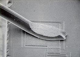
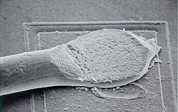
The following pictures detail wedge bonds and the possible problems encountered when trying to create a successful wire bond.
Both bonds pictured are well made and nicely deformed. The slight differences between the bonds are due to the use of different tools. Contact your localtool manufactures for details on different bonding tools and their applications.
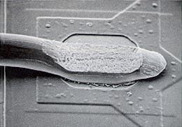
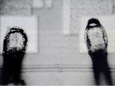
Both of the above-pictured bonds are good examples of heel cracking. This problem is often caused by brittle wire, or by excessive backbend motion. The back radius of the tool can also play an important role in preventing the heel from cracking.
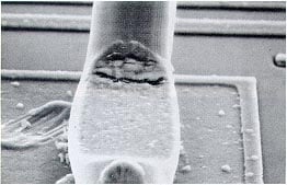
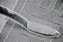
A over deformed (smashed) bond is shown. This is a result of too much bond force, too much heat (tool and/or workstation), or not enough tail length.
The burnt looking bonds above are a direct result of too much ultrasonic time. This crystallizes the wire decreasing bond strength and tool life.
The bond shown above is nicely made, however the nick in the wire above the bond is less than appealing. This type of nick is caused by improper tool selection, too much ultrasonic power during feed, misaligned clamps, or improper operator motion. This can also be a direct result of using the table tear method.
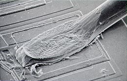
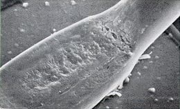
Notice the surface of the bond above. This is most likely due to a worn or dirty tool. Either clean your tool according to the manufacture’s suggestion, or replace it with a new one.
Pictures provided are courtesy of Gaiser Tool Company
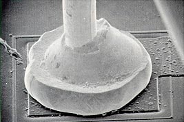
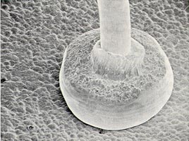
The following pictures detail ball bonds and the possible problems encountered when trying to create a successful wire bond.
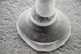
Above is a pair of well made ball bonds- capable of strong shear and pull tests.
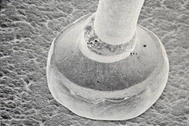
This off center ball, shown above, is a result of excessive torch voltage and/or a dirty torch wand. Voltage can be adjusted by the ball size potentiometer, which controls the voltage seen between the torch wand and the wire. The wand can be best cleaned with a small pencil eraser and rubbing alcohol.
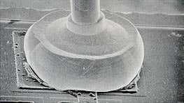
The picture above details a ball bond that has been made with a deformed ball. As you can see, the results are less than satisfactory. The pinched neck of the bond is easily broken and will result in poor pull tests.
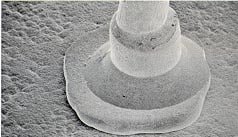
Another ball bond made with the use of a deformed ball. Notice how uneven the “collar” around the wire is.
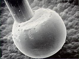
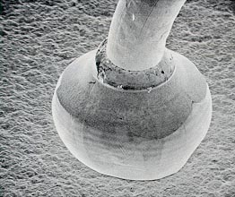
This bond has been made with an oversized ball. The setting was far too high on the ball size potentiometer.
This bond has been made with an undersized ball. The setting on the ball size potentiometer is too low and/or the tail length is too short.
This picture above shows a large ball that is under-deformed. Increase ultrasonic power, time, and force accordingly.
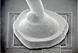
The rough surface seen on the top of this ball bond is due to an old, worn out tool. The ball appears to be well formed and bonded. It should pass wire pull and ball shear tests with high marks, however, it will fail a visual inspection.

Bonding Source 4 Townsend West, Suite 1 Nashua, NH 03063 USA (603)-595-9600 Fax: (603)-595-9601 E-Mail: info@bondingsource.com www.bondingsource.com |
About Bonding Source:
Bonding Source is a value added re-seller of epoxy pastes, epoxy films, and bonding wire used in microelectronics and RF/Microwave manufacturing. Bonding Source offers in-stock, immediate delivery and has no high minimum charges. Bonding Source stocks products from the best brands in the industry including Ablestik, Emerson Cuming, Epoxy Technology, and SPM. |
Deweyl Tool Company, Inc. 959 Transport Way |

SPT – Small Precision Tools 1330 Clegg Street |
Load all tools in tool tray with the point of the tool up. Do not place tools tip down in tray tip or tool damage will occur. Mix cleaning solution using water and sodium hydroxide. Mix (5) five parts water to (1) one part sodium hydroxide.
Place tool tray in 400ml beaker with enough Sodium Hydroxide cleaning solution to cover all tools completely. Place the beaker into the ultrasonic cleaner for approximately (3) three to (5) five minutes.
Transfer tool tray from cleaning solution beaker to 400ml beaker of hot water. Place beaker in ultrasonic cleaner for (3) three to (5) five minutes. Repeat this procedure with fresh hot water.
Complete the cleaning sequence with an alcohol rinse. Submerge the tool tray (2) two or (3) times in the alcohol solution and then blow-dry with clean dry air.
Warning: Do not use compressed air contaminated with moisture or oil.
It’s important to insure the tools are properly secured during the ultrasonic cleaning process. Damage will occur if the tools are not held properly during the ultrasonic cleaning.
Tool trays are available from DeWeyl Tool, Inc. at a cost of $75.00 each. Our tool trays safely hold 60 tools per tray.

Corporate Headquarters
1100 Cassatt Road
Berwyn, PA 19312
Ph: (610) 647-2121
E-Mail: info.corp@ametek.com
https://www.ametek.com/

Bonding Source
One Perimeter Road, Suite 200
Manchester, NH 03103 USA
Ph: (603)-595-9600
Fax: (603)-595-9601
E-Mail: info@bondingsource.com
www.bondingsource.com

Topline / Tanaka
95 Highway 22 W.
Milledgeville, GA 31061 USA
Ph: +1-800-776-9888
E-Mail: tanaka@TopLine.tv
www.TopLine.tv
Bonding Wire Catalog